Injector-Based Atmospheric-Pressure CVD (APCVD) Reactors
OK, this section is here in part because it’s something I worked on back in ancient times (1980’s and early 1990’s). But it is important to be aware that it is possible to make CVD work at atmospheric pressure with the appropriate precursors and equipment. You just have to apply the basic principles: if you’re at high pressure, gas-phase reactions are fast, so you need to use small volumes and high flows to keep the residence time small. In the rest of this section we’ll take a detailed look at how this can be done.
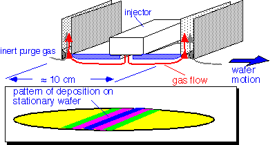
The linear injector reactor, typically used in an open system at atmospheric pressure, employs high gas velocities to achieve short residence times. By using multiport injection to prevent mixing of the reactant gases until they are dispensed into the deposition region, this type of reactor is able to use highly reactive mixtures such as silane and oxygen at atmospheric pressure while achieving good film quality.

Large gas flows are employed: typical total flows may be 25 slpm for a 200 mm injector. In addition, large flows of inert purge gas (typically nitrogen) are dispensed in between chambers and exhausted through the deposition region exhaust, to ensure that the reactive gases are contained within the desired regions of the reactor and removed rapidly.
To achieve uniform deposition on wafers or substrates, the substrates much be moved during deposition. This is usually achieved by placing the substrates on a flexible metal belt which carries them below a series of injectors; the wafers are removed at the end of the system and the belt passes through a cleaning process on its return path. Such reactors have the virtue of truly continuous processing: the transport belt runs at all times, with wafers loaded and unloaded using rollers. There is no load delay as is encountered in other reactor designs. For atmospheric pressure operation, there is also no pumpdown required. For film chemistries that lend themselves to the deposition conditions, very high throughput and low cost can be attained. The tradeoff is that the reactors are physically fairly large to permit wafers to heat up prior to entering the first deposition chamber and cool before unload, so a large number of wafers (e.g. on the order of 10 for a 200 mm wafer system) is in the reactor at any given time. Temperature setup is difficult due to the large reactor and low-thermal-conductivity transport belt.
Most processes generate copious particles in the gas phase, which are found as powdery deposits on the exhaust system and to a lesser extent on the chamber walls and ceiling. However, the reactors can be operated with excellent cleanliness, because of the large thermal gradients near the wafer: thermophoretic forces tend to prevent particles from reaching the wafer surfaces. [reference: "Particle Transport at Subatmospheric Pressures: Models and Verification" R. Periasamy, T. Yamamoto, R. Donovan and A. Clayton, Proc Contamination Control & Defect Reduction, 182 Meeting of the Electrochemical Society, Toronto, Oct 11-16, 1992, p. 48]
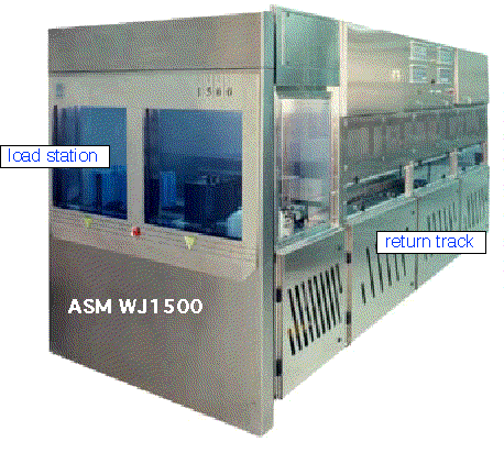
APCVD reactors have been widely used for the deposition of PSG and BPSG, where the high throughput and complete oxidation of the dopants were valuable, and reflow could be used to compensate for any deficiencies in deposited conformality. Commercial systems are available for deposition of various oxides, both silane-based and TEOS-based, from e.g. ASM; an example is shown below.

Return to Tutorial Table of Contents
Book version of the CVD Tutorial
