The RF in RFID: physical layer operation of passive UHF tags and readers
Daniel M. Dobkin
(revised Aug 2021)
2. Link Budgets and Range
What limits the range at which a tag can be read by a reader? To answer this question, we need to understand the four elements that determine read range:
- How much power can we transmit?
- How much power does the tag need?
- What happens to the signal power as it propagates from the reader to the tag?
- How does antenna behavior influence the power transmitted and received?
- How much power does the reader need to get from the tag to hear it?
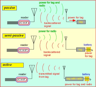
There are three types of UHF tags: passive, semi-passive, and active. Passive tags use the signal received from the reader to power the IC, and vary their reflection of this signal to transmit information back to the reader. Passive tags are the most common in cost-sensitive applications, because, having no battery and no transmitter, they are very inexpensive. Semi-passive tags, sometimes known as battery-assisted passive tags, use a battery to power the tag electronics, but also depend on a reflected signal for communications. Active tags are full-featured radios with their own transmitting capability independent of the reader. In this article we will consider only passive tags, the most commonly-encountered, and range-challenged, of the three types.
[click for animation]
1] How much power can we transmit?
The amount of power a radio can transmit is usually limited by one or more of three constraints: cost, power consumption, and government regulations. In the case of unlicensed operation in the US ISM band, the Federal Communications Commission, in part 15 of its regulations, limits transmit power to 1 watt (in addition to several other constraints). A typical stationary RFID reader, affixed to a portal or conveyor and powered from 60 Hz mains power, is likely to permit transmit power up to the legal limit. A portable or handheld reader may transmit lower power to conserve battery life. In our estimates we will assume the US maximum legal output power of 1 watt or 30 dBm.
2] How much power does the tag need? how much power arrives at the tag?
Published results [1,2] suggest that typical tag integrated circuits require around 30-50 microwatts to operate, and recent (2006/2007) commercial tags appear to achieve performance corresponding to this power consumption. It seems reasonable that as the tag moves away from the reader antenna, the tag will receive less power from the reader, and that at some point too little power would be available to power the tag. Below we shall attempt to quantify this statement so as to make useful predictions.
3] What happens to the signal power as it propagates from reader to tag?
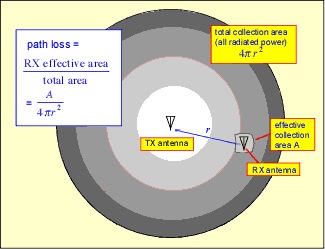
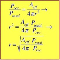
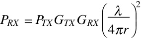
The simplest way to estimate the power received by an antenna is to imagine that the transmitter sends the signal equally in all directions: that is, to assume that the reader uses an isotropic antenna. (Isotropic antennas are not actually possible to build, and if they were readers would rarely use them, as tags are usually located in well-defined directions relative to the reader and power radiated elsewhere is thus wasted. We will examine shortly how more realistic antennas affect our results.) At any distance r from our ideal isotropic antenna, the signal power is thus distributed uniformly over the surface of an imaginary sphere. If we imagine that a receiving antenna collects the power impinging on some effective area A, we can then calculate the maximum power that antenna could receive:
[click for animated version]
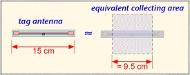
We can now estimate how far a tag can be from an isotropic reader antenna and still receive enough power to operate. If the reader can transmit 1 watt (30 dBm), and the tag needs about 30 microwatts (-15 dBm), we are allowed about 45 dB of path loss before the tag runs out of steam. In order to figure out the corresponding distance, we need to say something about the collection area A. For a typical passive tag (the Alien Technologies I-tag is schematically shown below) with a length of around 15 cm, a reasonable guess might be an area a bit less than 15 cm on a side; the figure indicates an equivalent area of around 90 square cm.
(It is possible to justify this estimate in detail but that would take us far afield. See for example chapter 5 in RF Engineering for Wireless Networks, Elsevier 2004, by the present author, or Antenna Theory (3rd edition), Balanis, Wiley, 2005, chapter 2.)
Plugging the area and allowed path loss into the expression for the distance gives us an estimate of power-limited tag range (note the calculations are done in meters and watts):
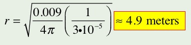
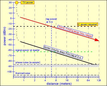
A graphical view of what's going on is shown below. The power received by the tag falls off as the square of the distance (6 dB per octave), except very near the reader antenna where things are too complex to bother with here. At 5 meters or so, the tag power has fallen to just enough to power the IC.
[click for animated version]
We can then regard the tag as a radio with a power about equal to that it receives (give or take a few dB), and look at the power that could be received by the reader. Because most real channels are reciprocal, the path loss in both directions is symmetric, so we get around (30 - 2(45))=-60 dBm received signal at the reader when the tag is at 5 meters range.
It's worth noting that larger tag power consumption means shorter range. If the tag IC requires 300 instead of 30 microwatts, the range is reduced by a factor of about the square root of 10 or 3.2: that is, about 1.5 meters. For 0.5 W transmit power, we'd expect a range of around 1.1 meters. Similarly, lower tag turn-on power gives better range. The Impinj R6 tag datasheet, current 2021, indicates read sensitivity of about -22 dBm or about 6 microwatts, which provides read range exceeding 10 meters in reasonably clear environments.
4] How does antenna behavior influence the signal power?
Real antennas don't radiate equally in all directions. This is generally a desirable trait: in RFID applications, tags are usually placed in specific locations with respect to an antenna, so there's no point in wasting power where there's no tag.
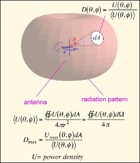
An antenna generally radiates a different amount of power in each direction. The power density U is the power in a given solid angle, and varies with direction. The directive gain is the ratio between the power density in a given direction and the average power density. The ability of an antenna to concentrate the radiated power in specific directions is known as the directivity (often maximum directive gain or just gain). The directivity is defined as the maximum value of the power density divided by the average. An antenna with a gain of 3 delivers 3 times more power to an antenna (like a tag) located along the direction of maximum power density than an isotropic antenna (like the one considered above) would.
It is important to note that, despite the implications of the terminology, antennas don't actually add any power to the signal: they're just passive devices. Formally we should note that 'gain' includes radiative efficiency, whereas directivity does not, but this is not generally an issue for reader antennas, where efficiency is very high. Gain is often measured in dB with respect to an ideal isotropic antenna, denoted dBi.
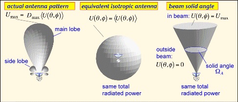
Highly-directional antennas put most of their energy into a main beam, with smaller sidelobes (typically 15 dB or so less than the main lobe for the sort of antennas used in RFID). Nearly-isotropic antennas like dipoles can be regarded as radiating an equivalent isotropic power everywhere; directional antennas can be approximated by assuming all the power goes into a beam with some angular width, and no power goes in other directions.
The effective isotropic radiated power (EIRP) is the power that would have been radiated by an isotropic antenna with the same power density as the real antenna in the direction of maximum gain: thus, it is calculated by adding the antenna gain to the actual radiated power. The FCC in the US regulates in terms of EIRP by reducing the allowed power when the antenna gain exceeds 6 dBi for unlicensed operation. The term effective radiated power (ERP) is also used, but unfortunately the definition of this term is ambiguous: some authors use it synonymously with EIRP, but others (including the FCC) treat it as referencing an ideal dipole antenna, and thus differing by about 2 dB from EIRP.
When directional antennas are used to form a radio link, there are beneficial effects on both ends of the link (if the antennas are properly pointed!). The transmitted power in the direction of the receiver is increased by the antenna gain, and the effective area of the receiver is also increased.
(It is not trivially obvious that the latter ought to occur; it is demonstrated by assuming that the system is reciprocal: that is, it shouldn't matter if we switch the roles of transmitter and receiver. See any text on antenna theory for more details.)
If we use a directional antenna for the reader TX and RX functions, we improve both the signal delivered to the tag and that received from it. An antenna with 10 dBi of gain on a 1-watt transmitter would provide 30 microwatts of power to a tag at 16 meters -- but it would also be illegal for unlicensed operation in the US.
FCC part 15 requires that for antenna gains greater than 6 dBi, the power be reduced accordingly to maintain a fixed EIRP. The maximum permissable gain with full power is 6 dBi or a factor of 4, corresponding to about a factor of 2 increase in range vs. an isotropic antenna. We obtain a predicted range of around 10 meters, in good agreement with measured ranges on vintage-2006 passive UHF tags.

[click for animated version]
So far we've assumed tag range is limited by the power delivered to the tag, and this is generally the case for passive tags. However, it is important to note that the reflected signal from the tag falls rapidly with distance: the power at the tag goes down as the square of the distance, and the reflected power that reaches the receiver is again reduced by the square of the distance (because the tag is almost an isotropic reflector -- more like a party ball than a hand mirror!), so the power at the receiver decreases as the fourth power of the distance. For distances larger than about 20 meters, achievable with battery-assisted (semi-passive) tags, one must attend carefully to receiver design to minimize noise. A thermal-noise-limited high-quality receiver can achieve backscatter-limited range of 50-100 meters with such tags.